Zener diodes
by Cor van Rij
- Introduction
- Zener Characteristics
- The Diode Zener
- The Complementary Zener
- The Vbe multiplier (1)
- The Vbe multiplier (2)
- The Opamp Superzener
- Literature
Introduction
Zenerdiodes are very usefull devices that do have many applications in electronics. For example you can use them in:
- Voltage reference
- Overvoltage protection
- Speeding up comparators by limiting RC times
- etc
However, this tiny little device does have intrinsic problem associated to it... you never have the right value at hand. It is often at 2200h on Saturday evening when this zenerdiode is the single last component that is needed to complete another master piece of electrical engineering.
Of all the applications of the zenerdiode, the usage as a voltage reference is the most common, hence we will focus on this particular application.
In this article we'll first look at some basic characteristics of Zenerdiodes and afterwards we will look into some alternative circuits that can be used to provide.
Zener Characteristics
As any semiconductor device there are many paramters that can be used to characterize a zener diode. Examples paramters are: maximum forward current If, maximum reverse current Ir, dynamic resistance rd, Maximum power dissipation Pmax, temperature stability mV/oC, etc, etc.
For use as voltage reference in most circuits luckiliy enough only a few paramters are necessary. In this paragraph we will highlight the most important of them.
In the following graph the more or less normal characteristic of a zenerdiode is displayed.
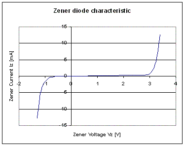 This graph clearly show the most important paramters: VDz which is circa 3.2V at 3mA. Less obvious is another important paramter, the dynamic resistance rD of the zener diode. The dynamic resistance is the slope of the curve in the top-right quadrant. The formula to caluclate this is: rD = (V1-V2)/(I1-I2). In this example the dynamic resistance is thus approximately: (3.5-3.2)/(15mA-3mA)= 25 Ohms.
The Diode Zener
This is by far the most simple replacement circuit for a normal zener diode. However, the simplicity of this circuit comes with limitations (there is no such thing as a free lunch). The two main limitations are:
- The reference voltage of D1 - D4 is determined by the current through the diodes. The current through the diodes is determined by R1. Since the voltage is unstabilzed the current will vary and thus the reference voltage and the output voltage will follow.
- The Temperature instability of the both diodes can be added together. Although realitively the variation will thus stay the same the absolute value will increase.
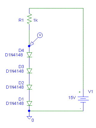
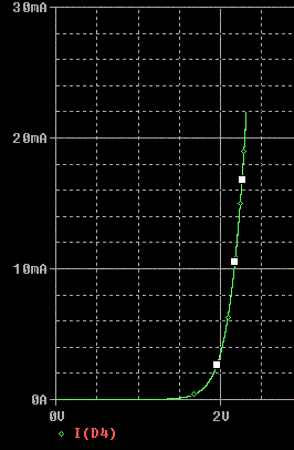 As can be seen from the graph the zener voltage is circa 2.4V. The dynamic resistance of the constructed zenerdiode is circa 17 Ohms. The temperature variation vannot be derived from this graph. However the temprature variation for a normal diode is circa 2mV/oC. So in this case it will be circa 8mV/oC.
The complementary zener
The original of this circuit is found in reference 1). It is a simple circuit build with two complementary transistors. The zener voltage is fixed and cannot be altered. The Zenervoltage is circa 1,5V.
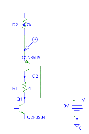
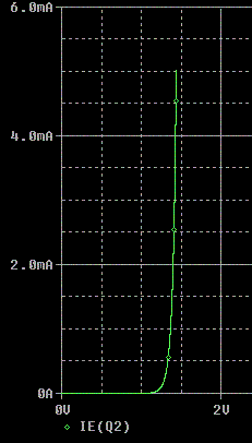 The calculated dynamic resistance is circa 13 Ohms. The maximum power dissipation is circa 500mW if used with low power transistors like 2N3904/2n3906 or BC547b/BC557b.
Improved circuit (2)
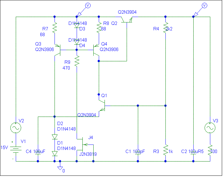
The circuit can be further imrpoved by using more stable current sources. Although FETs are easy to setup as a current source they are difficult to control because of the large tolrances and they are realivetly sensistive to drain-source voltage variations. In the next circuit circuit the current sources are swapped for common emittor current sources.
|
Input Voltage |
Output Voltage |
Rejection Ration |
Output current |
Output Voltage |
Output resistance |
| Figure 1 |
10V - 20V |
6.24V - 6.85V |
17x |
17mA - 110mA |
6.61V - 6.56V |
505mOhm |
| Figure 2 |
10V - 20V |
6.94V - 6.98V |
250x |
21mA - 118mA |
6.99V - 6.95V |
410mOhm |
| Figure 3 |
10V - 20V |
6.88V - 6.89V |
625x |
20mA - 117mA |
6.90V - 6.86V |
400mOhm |
Literature
As inspiration to start this research the following sources were used
- Hobby-Elektronik-Audion, section Zenerdioden
- Zener effect and Zener diodes
- Zener diode tester


