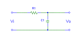
The impedance of R1= R and the complex impedance of C1 is given by ![]() and the output voltage is given by:
and the output voltage is given by: ![]()

| (1) |
If we multiply the equation above with 1 or in this case with ![]() we finally get the transfer function:
we finally get the transfer function:

| (2) |
Now, any complex number can be written in a number of ways. One of the most common ways to write a given complex numkber C is: ![]() . This is actually a vector in O(0,0) with a certain length and a certain angle. The Modulo of the complex number C is the length, while the Argument of of the complex number C is the angle of the vector.
. This is actually a vector in O(0,0) with a certain length and a certain angle. The Modulo of the complex number C is the length, while the Argument of of the complex number C is the angle of the vector.
The Modulo is given by:
|
| (3) |
And the Argument is
|
| (4) |
|
|
|
| (5) |
With the result of (5) we can write the transfer function (2) a complex number C and we can calculate the Modulo and the Argument from it. The Modulo is given as:
|
|
|
| (6) |
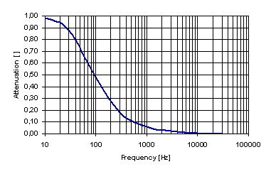
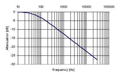
 |  |
| Transfer function of a single stage RC filter. | Transfer function of a single stage RC filter, log. |
|
|
|
| (7) |
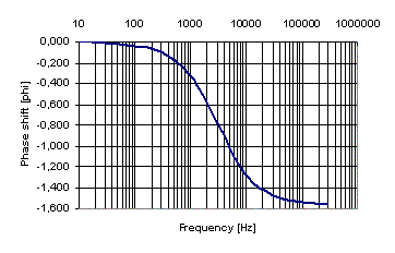
 |  |
| Transfer function of a single stage RC filter. | Transfer function of a single stage RC filter, log. |