Building electronic equipment is fun! Especially if you have access to some instruments that will help you troubleshooting. The best instrument available to everyone are your own brain and your own senses. When you smell smoke you have a problem and with your eyes you can see where it is comning from. Even without smoke you have the "finger-test"; if it is too hot to touch you have a problem (DO NOT try this with equipment connected to mains, whether ~115V or ~230V or any voltage above 24V!). The standard external instrument that everyone should have is a volt-current-ohm meter (VOM). This will help you measure voltages and currents. In the resistance mode it will help troubleshooting short-circuits in your circuit, test diodes and resistors, check for open connections in inductors and cables. Nowadays they're available dead cheap. Check out for example FutureLec (not associated!). With a price of 5$ it is hardly worth buying a replacement battery. Some people even use them as a cheap alternative for ready DVM modules. Check out the web-site of Hans Summers. These digital VOM do have an internal resistance which is typical like 10MOhm/Volt and an accuracy of <5%.
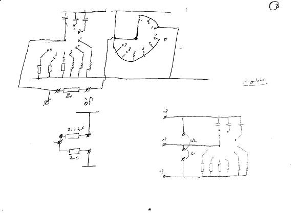
The next thing you probably want to measure is value of a certain capacitor or if you planning on building radios the value of an inductor. Unfortunately most of the cheaper multi-meters, which are perfectly adequate for the job, don't have this option. The more expensive models do have an option for measuring capacitance. However, only the really expensive models do have the ability to measure the inductance of a coil. This is where the bridge circuit comes in. Put an unknown capacitor in series with a capacitor with a known value. Take two resistors (one adjustable) and vary the ratio until you do not measure a voltage difference between the capacitors and the resistors. If you want to have more information check it 1,2,3, in the literature below.
OK, enough talking. Time to get to the interesting part. Below you will see the block diagram of the device. An oscillator on the left, an audio transformer salvaged from an old transistor radio, the actual bridge circuit (the taper resistor and the two condensators, one as reference the other as unknown) and finally an amplifier with meter reading. It can easily been seen that if teh ratio RA/RB and RC/RD are equal, there will be no voltage across the bridge.

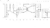
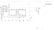
If we now go to the actual circuit diagram, the block diagram is easily to recognize. The astable multivibrator (AMV) with the two transistors on the right is the oscillator. The 10K potmeter are resistor RA and RB, of the two condensators one is the reference, the other is the "unknown". The right half of the circuit is the detector with a simple old VU-meter as indicator.

The AMV oscillates a at a frequency of f=1/(2* 0.69*R*C), which is circa 609Hz. A transformer in the collector of one of the transistors is used to isolate the bridge from the oscillator. In this way it is possible to connect the node between two resistors to earth and use the other bridge connection to measure the voltage difference e.q. the bridge unbalance.
A J-Fet 2N3819 is used as a buffer with a high input impedance and a low output impedance. The input impdeance here is solely determined by the 1MOhm resistor. This resistor is required sothat the gate sees a path to earth.
Finally an opamp is used to multiply the signal 100x or 10x depending on the resistor value used in the feedback leg. In the final build a SPDT switch was used sothat the sensitivity could be changed between normal and '10x'. This feature is handy sothat in the 'normal' setting the dip can quickly be found and the final tunining is done with the '10x' setting.
The condensator in the feedback leg is used sothat the DC amplification is 1x. The diodes in rectifier are germanium diodes, with their lower Vd a very small dead range is created.
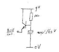
On the right you can see a simple RC lowpass filter in the powerline of the detector. This is used to isolate the detector from the switching noise from the AMV (see also improvements). Later on, I decided to improve this with a single transistor. While the original filter does have a cut-off frequency of fc=1/(2*pi*R*C)= 28Hz the modified circuit does have a cut-off frequency of fc=1/(beta*2*pi*R*C)= 0.013Hz an improvement of more then 2000x.
|
|
|
Click to enlarge
|
Click to enlarge
|
|
|
|
|
|
|
Click to enlarge
|
Click to enlarge
|
Click to enlarge
|