Stereo Infrared Headset
By Jeroen Bastemeijer,
Matthijs de Gelder,
Anthoon van Luxemburg
& Cor van Rij
This is an assignment we had to do when still at university. Being stubborn as we all were we choose what we thought was the most difficult and most fun from the available first years topics. Since, it is 10+ years ago, I only do have paper copies left from the circuits. So, I am sorry for the bad quality but it is all there is left now.
So, the first question we needed to answer was which modulation scheme we wanted to use and how to encode the left and the right channel. Initially we thought about transmitting a digital signal. Left and right channel Sample&Hold, combined with an ADC and a means to multiplex the data in frames to differentiate between left and right channel, or something like that. However, since it was intended as a (strictly) analog excercise and the time frame was limited the digital approach was soon abonded. Instead we looked at to conventional approaches, frequency modulation and amplitude modulation. Unfortunately, the IR LED we had at our dispose did have a high self capicitance, thus severly limiting the possibly bandwidth. Finally we decided on a novel form of AM, Pulse Amplitude Modulation (PAM) with the strong pulse encoding one channel and the weak pulses encoding the other channel...
So, how does it work you might wonder? At idle we transmit pulses at a strength of 50%, left channel idle is 75%. If the left channel signal is at the positive top we transmit a pulse at 100%, if the left channel signal is negative minimum we transmit a signal of 50%. Same for the other channel. If right channel signal is at positive top we transmit a pulse at 50%, if right channel signal is negative minimum we transmit a signal of 0%. Got the picture? To make sure the integrator doesn't drift (more about this later), we send an idle signal (=50% pulse) between left and right channel.
 |
Click to enlarge
|
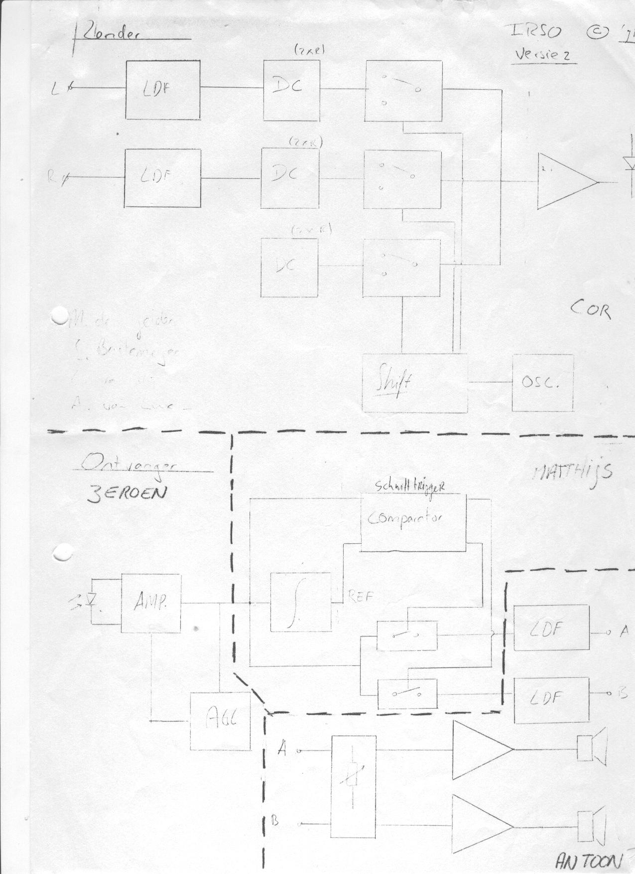
To the left you can see the highlevel diagrams of the transmitter(=zender) and the receiver (=ontvanger). (The dashed lines indicate the split we made so everyone had it's own part to focus on.
The transmitter, eventhough the modulation scheme may sound very complex at first, the actual transmitter is in fact ridiculously simple. On the left site of the diagram are the inputs of the Left and Right audio channel. First we send these signals through a low pass filter (LPF), to prevent any aliasing in the next stage when we chop the audio signal into small pieces. We then add a DC shift to the signal 75% of Vcc for the left channel and 25% of Vcc for the right channel. Also we create an idle signal of 50% Vcc. Then we have three electronic switches that switch continuously between Idle, Left, Idle, Right, Idle, Left, etc. This signal is then send to the final stage, a power amp that converts this signal to current pulses for the IR emitter.
As you can see the transmitter is actually not very diffucult. As usual, it is the receiver were the real complexity is... The receiver starts with a high sensitive IR diode that is used to receive the emitted IR signal. This is then amplified almost 70x and an Automatic Gain Control (AGC) is used to prevent the receiver from clipping when the received signal is from a nearby, strong, source.
The next section in the receiver is the stereo-decoder. The received signal is fed into an integrator. This subcircuit averages the signal over long time and provides a reference to the schmitt-trigger to decide which signal is stronger then average and thus left channel and which is weaker and thus right channel. Using an integrator guarantees that also in case of a signal with varying strength a usefull reference signal is available for the schmitt-trigger. The output from the schmitt-trigger is then used to switch the signal to the left or right channel via an electronic switch.
The 'audio'-signal now available consist of a continuing series of pulses from which the peak-amplitude corresponds with the amplitude of the original audio signal. Looking into the frequency domain the signal can be seen as the audiofrequency, with a higher frequency signal, the frequency of the oscillator in the transmitter. Yhis higher frequency signal is urrounded by two sidebands of teh adudio signal. The original signal is recovered by feeding it through a lowpass filter. Finally, the signal is amplified and fed to a speaker or a headphone
 |
Click to enlarge
|
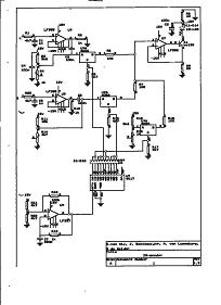
So the reall-stuff. On the left you see the electronic circuit of the transmitter. Now we've discussed the various blocks of the transmitter before you van probably recognize most of them. The two opamp's on the top left are buffers after the two simple 1 order Low-pass-filter. Probably the component values are incorrect, using the basic formula fc= 1/(2*pi*R*C) you get a cutt-off frequency of around 33.8KHz. This most likely must be something like 3.3 KHz and value for C1 and C5 of 100nF... The opamps function as 1x buffer to protect the LPF from all switching action which is done thereafter. Before the actual switching is done a DC voltage is added, via R3, R4 and R11,R14 respectively. Also the idle voltage created via the resistor combination of R13 and R16. The CMOS 4066 offers 4 electronic switches in a standard 14-pin DIL housing, of which only 3 are used in this application. The resulting signal is summed via the three resistors of 100 ohm and are then offerend to the power amp stage. This stage converts the voltage to a current that is send through 3 IR emitter LEDs. This works as follows; the opamp tries to keep the voltages at the inverting (-) and the non-inverting (+) input equal. So imagine we offer a voltage of 2.2V to the non-inverting input, the opamp keeps the inverting input at the same voltage so a voltage of 2.2V over a resistor of 22 ohm, this implies a current of 100mA. Since Ie equals Ic the same voltage flows through the LEDs as well. The RC netwerk on top of the diodes is intended to keep all the switching noise from creeping in the rest of the circuit and creating havoc there.
A note on the resistor voltages for the left, right and idle signal. If you did the arithmatic you will have noticed that this values in no way give you the 3/4 Vcc, 1/2 Vcc and 1/4 Vcc. This is not by accident. The reason is (every) opamp has limtations on it's input stage and limitations on the output voltage swing. Also in this case we want have enough headroom to bias the three IR-LEDs. So the actual topvoltage is not Vcc, but is circa 20% of Vcc. For the actual function it doesn't much matter, it is the ratio between the voltages that count. If you want to make sure you squeesh the last drop of performance from the IR-LEDs you can tweak the 22 Ohm resistor in the emittor of Q1.
 |
Click to enlarge
|